⚠️ This content has been written a long time ago. As such, it might not reflect my current thoughts anymore. I keep this page online because it might still contain valid information.
Playing with a ESP8266 WiFi module
— Clermont-Fd Area, France2022-07-25 // I proofread this article and fixed some links.
2015-03-26 // I open-sourced EspWiFi, a Arduino driver for the ESP8266 WiFi Module.
I started to play with some Arduino-based technologies after having built my very own Arduino board at AcoLab1 a few weeks ago. I’ve been working on a project to connect a coffee machine to the Internets. In this article, I introduce the ESP8266 WiFi module, courtesy of @disk_91, from a “user perspective”.
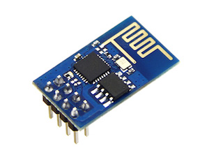
I have a ESP-01 module (ESP8266 being a microchip with its own built-in TCP/IP stack). It is possible to program and use this module without any other board but the module isn’t super powerful. In case you’re interested, nodemcu is a lua-based interactive firmware worth taking a look! The alternative approach is to pair this module with another micro-controller like an Arduino. That’s how I want to use this WiFi module in the future.
We can get started with just a computer, though. A FTDI is needed to connect the module to it. FTDI is a common name for USB-to-TTL (or serial) converter, FTDI being the company making and selling these products.
Wiring
As mentioned previously, I have a ESP-01, which has 8 pins: VCC, GND,
CH_PD, TX, RX, RST, GPIO0, and GPIO1. Wiring the module is not
super complicated:
VCCneeds 3.3VCH_PDhas to be pulled-up (meaning it has to be connected to 3.3V as well)GNDis connected to FTDI’sGNDpinRXis connected to FTDI’sTXpin, because we want to create a loop:RX->TX=>RX->TXTXis connected to FTDI’sRXpin- other pins are left floating
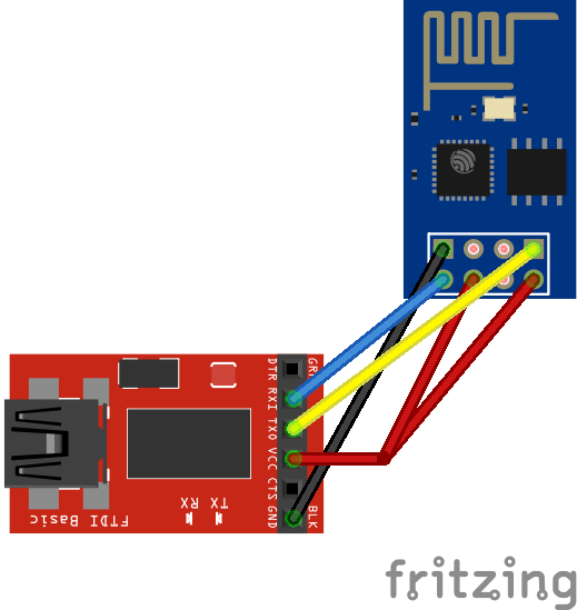
It’s important to use a 3.3V power supply and not 5V. In terms of power consumption, this module requires more than 200mA. This is also rather important because a lack of intensity causes various issues (the module gets unstable and it’s annoying to debug).
I read that CH_PD should be pulled-up with a resistor (from 3k to 10k
Ohms), however it did not work for me so I connected this pin to VCC 🙈
Talking to the module
We can use screen or any tool that can talk to a serial interface to connect
to the module using an FTDI. This is how I did it:
screen /dev/tty.usbserial-A50285BI 9600
Depending on the firmware version, baud rate is different: 9600, 57600 or
115200. This is another thing that can cause communication issues. You should
try different baud rates, it will either work, display gibberish, or simply
fail… 115200 seems to be the default value.
Once you find the right baud rate, you can send a first AT comand to the
module. The following command asks the module whether it is up:
AT
It should respond with OK. The AT command set is quite large, I cover a
few commands in this post but feel free to try them all.
At this point, I could communicate with the module but it wasn’t super stable. I read that it could be an issue with old firmware (related to the default baud rate) so I looked into flashing my ESP-01 with a more recent firmware.
Upgrading the firmware
I downloaded the most recent official firmware from espressif/esp8266_at. In
order to flash the module, GPIO0 must be pulled-down by wiring its pin to
GND. After that, esptool can be
used:
$ esptool.py -p /dev/tty.usbserial-A50285BI write_flash 0x0000 boot_v1.1.bin \
    0x01000 user1.bin 0x7C000 esp_init_data_default.bin 0x7E000 blank.bin
boot_v1.1.bin, esp_init_data_default.bin, and blank.bin don’t really
change between versions but user1.bin does! Recent firmware apparently support
cloud updates, but I haven’t tried that yet.
In order to change the baud rate, connect to your module and send the
AT+CIOBAUD command with a value (57600 in this case):
AT+CIOBAUD=57600
Now that the communication with the module is OK, let’s join an access point.
Joining an access point
I used pyesp8266 to talk to the module and connect to an Access Point. This tool offers a thin abstraction layer on top of some more AT commands:
$ python esp8266test.py <serial_port> <ssid> <password>
A few hints in case something goes wrong:
- Is the red LED on the module lit? If it is not, the board is not getting power.
- When trying to issue commands, do you see the blue LED on the module blinking? If not, check the RX/TX connections. If the LED is constantly lit, then one of the connections is wrong (probably RX/TX).
- Are you seeing gibberish? Try a different baud rate. In one of the provided
scripts, run the
AT+CIOBAUDcommand first (modify the script). - The script gets stuck on the
AT+CWJAPcommand? Increase the timeout in the script (default is:5seconds, mine works better with10).
Running a TCP server
As I wrote previously, this module embeds a TCP/IP stack, which allows the
module to open a socket and listen to a given port (among other things). This is
doable by manually sending AT commands or by using the esp8266server.py
script (bundled with the pyesp8266 tool).
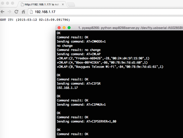
This script runs a simple TCP server on port 80 by sending the following AT
commands:
# allow multiple connections
AT+CIPMUX=1

# run a TCP server on port 80
AT+CIPSERVER=1,80
The script also sends the AT+CIFSR to retrieve the IP address. We can use this
IP to connect to the server. In a web browser, we would see the message GOT
IT! as depicted in the screenshot above.
Links
Because nothing would have been possible without these articles and useful resources, thanks!
- Getting started with the esp8266 and Arduino
- noob’s guide to ESP8266 with Arduino Mega 2560 or Uno
- ESP8266 Teensy Time
- ESP8266 WiFi module
- ESP8266 - Upgrading the Firmware
- ESP8266 Community Forum
- ESP8266 Electrodragon
- esp8266/esp8266-wiki - Toolchain @ GitHub
- ESP8266 WiFi Module Quick Start Guide
- ESP8266 Offical AT+ Command @ GitHub
-
AcoLab is a hackerspace based in Clermont-Fd, France. ↩
ℹ️ Feel free to fork and edit this post if you find a typo, thank you so much! This post is licensed under the Creative Commons Attribution-ShareAlike 4.0 International (CC BY-SA 4.0) license.