Bare-metal Raspberry Pi 2 programming
— Clermont-Fd, FranceLast week-end, I started to play with ArvernOS (my very own 64-bit kernel) and one of the Raspberry Pi 2 I had in a drawer (32-bit architecture unfortunately but that’s a story for another time).
After a few hours, I was able to run ArvernOS with most features disabled on real hardware (getting it to run in QEMU was surprisingly straightforward). In the following, I’ll explain the boot sequence of a Raspberry Pi 2 and show how it works using an example.
Boot sequence
When we power on a Raspberry Pi 2, the CPU is not yet active, only the GPU
(VPU) is. The boot sequence is a
multi-stage sequence that loads and executes different programs sequentially.
The GPU starts by executing the first stage bootloader stored on the board (in
ROM) which, among other things, will attempt to read the SD card and load the
second stage bootloader named bootcode.bin. The code contained in
bootcode.bin will load the main (GPU) firmware named start.elf as well as
another file named fixup.dat, both located on the SD card. The latter is used
to configure the SDRAM depending on the hardware. The start.elf file contains
the code to display the rainbow splash when we have a screen connected to a
Raspberry Pi but its main task is to boot the CPUs and load the kernel code.
Both bootcode.bin and start.elf attempt to read a config.txt file, which
is an optional but extremely useful configuration file. For example, we can add
uart_2ndstage=1 to this file to get diagnostic information on UART0 (serial
port). We can also specify the kernel code we want to run (the default kernel
file being kernel7.img on a Raspberry Pi 2).
Quick example with U-Boot
Let’s try to compile and execute U-Boot to understand how things work. U-Boot is a fairly small bootloader used in many embedded devices, and it normally attempts to load an actual Operating System. U-Boot runs a command-line interface on a serial port too so we’re going to leverage this feature and only load U-Boot.
First, we need to download the bootcode.bin, fixup.dat and start.elf files
from this repo and
put them on the main
FAT32 partition of
a SD card. These files are provided by the Raspberry Pi Foundation, which means
most of the early boot sequence is done for us. I know about this alternative
second stage bootloader
project but I am not sure why
we’d use it to be honest.
$ ls /Volumes/SDCARD/
bootcode.bin*  fixup.dat*  start.elf*
The next step is more interesting. We need something for the start.elf program
to complete successfully. In this example, we want to use U-Boot so let’s
compile it. I personally used the Docker-based ArvernOS
toolchain
for that:
$ git clone git://git.denx.de/u-boot.git
$ cd u-boot
$ docker run -it --rm -v $(pwd):/app willos/toolchain make rpi_2_defconfig
$ docker run -it --rm -v $(pwd):/app willos/toolchain make
  [...]

  LD      u-boot
  OBJCOPY u-boot.srec
  OBJCOPY u-boot-nodtb.bin
  SYM     u-boot.sym
  COPY    u-boot.bin
Once finished, we can move the generated u-boot.bin file to the SD card as
well. We’re almost there, all we need is to create the config.txt file with
the following content on the SD card:
# Output debug information from `bootcode.bin` and `start.elf`
uart_2ndstage=1
# Configure which file should be loaded by `start.elf`
kernel=u-boot.bin
The SD card should now have five files:
$ ls /Volumes/SDCARD/
bootcode.bin*  config.txt*  fixup.dat*  start.elf*  u-boot.bin*
Let’s connect a USB to TTL serial cable
(FTDI) between the Raspberry Pi 2 and our
main computer. We can now open the serial port (with screen -L
/dev/tty.usbserial-A900HHN1 115200 for instance), put the SD card in the Pi and
power it on.
After a few seconds, we should see the debug information from the boot sequence first:
Raspberry Pi Bootcode
Read File: config.txt, 34
Read File: start.elf, 2878340 (bytes)
Read File: fixup.dat, 6729 (bytes)
MESS:00:00:00.949118:0: brfs: File read: /mfs/sd/config.txt
MESS:00:00:00.953246:0: brfs: File read: 34 bytes
MESS:00:00:00.967599:0: HDMI:EDID error reading EDID block 0 attempt 0
[...]
MESS:00:00:01.029675:0: HDMI:EDID giving up on reading EDID block 0
MESS:00:00:01.034965:0: HDMI:EDID error reading EDID block 0 attempt 0
[...]
MESS:00:00:01.098164:0: HDMI:EDID giving up on reading EDID block 0
MESS:00:00:01.115837:0: brfs: File read: /mfs/sd/config.txt
MESS:00:00:01.119959:0: gpioman: gpioman_get_pin_num: pin LEDS_PWR_OK not defined
MESS:00:00:01.136991:0: gpioman: gpioman_get_pin_num: pin WL_LPO_CLK not defined
MESS:00:00:01.142693:0: gpioman: gpioman_get_pin_num: pin BT_ON not defined
MESS:00:00:01.149373:0: gpioman: gpioman_get_pin_num: pin WL_ON not defined
MESS:00:00:01.330719:0: gpioman: gpioman_get_pin_num: pin DISPLAY_DSI_PORT not defined
MESS:00:00:01.338144:0: gpioman: gpioman_get_pin_num: pin LEDS_PWR_OK not defined
MESS:00:00:01.344167:0: *** Restart logging
MESS:00:00:01.348055:0: brfs: File read: 34 bytes
MESS:00:00:01.352881:0: hdmi: HDMI:EDID error reading EDID block 0 attempt 0
[...]
MESS:00:00:01.421187:0: hdmi: HDMI:EDID giving up on reading EDID block 0
MESS:00:00:01.426996:0: hdmi: HDMI:EDID error reading EDID block 0 attempt 0
[...]
MESS:00:00:01.495406:0: hdmi: HDMI:EDID giving up on reading EDID block 0
MESS:00:00:01.500937:0: hdmi: HDMI:hdmi_get_state is deprecated, use hdmi_get_display_state instead
MESS:00:00:01.509687:0: hdmi: HDMI:hdmi_get_state is deprecated, use hdmi_get_display_state instead
MESS:00:00:01.519522:0: Failed to open command line file 'cmdline.txt'
MESS:00:00:01.555553:0: brfs: File read: /mfs/sd/u-boot.bin
MESS:00:00:01.559432:0: Loading 'u-boot.bin' to 0x8000 size 0x76ea4
MESS:00:00:01.569756:0: No kernel trailer - assuming DT-capable
MESS:00:00:01.574005:0: brfs: File read: 487076 bytes
MESS:00:00:01.578852:0: Failed to load Device Tree file '?'
MESS:00:00:01.584503:0: gpioman: gpioman_get_pin_num: pin EMMC_ENABLE not defined
MESS:00:00:01.592129:0: uart: Set PL011 baud rate to 103448.300000 Hz
MESS:00:00:01.598961:0: uart: Baud rate change done...
MESS:00:00:01.602394:0: uart: Baud rate change done...
MESS:00:00:01.608047:0: gpioman: gpioman_get_pin_num: pin SDCARD_CONTROL_POWER not defined
I did not have a monitor connected when I ran this example so there were a few HDMI related errors. Near the end, we can read the following lines:
MESS:00:00:01.555553:0: brfs: File read: /mfs/sd/u-boot.bin
MESS:00:00:01.559432:0: Loading 'u-boot.bin' to 0x8000 size 0x76ea4
Shortly after U-Boot should write to the serial port too and we can enter the built-in shell by pressing a key:
U-Boot 2021.01-00688-g184aa65041 (Jan 23 2021 - 10:56:09 +0000)

DRAM:  948 MiB
RPI 2 Model B (0xa01041)
MMC:   mmc@7e202000: 0
Loading Environment from FAT... *** Warning - bad CRC, using default environment

In:    serial
Out:   vidconsole
Err:   vidconsole
Net:   No ethernet found.
starting USB...
Bus usb@7e980000: USB DWC2
scanning bus usb@7e980000 for devices... 3 USB Device(s) found
       scanning usb for storage devices... 0 Storage Device(s) found
Hit any key to stop autoboot:  1
U-Boot>
Sweet!
From there, we can print the U-Boot version:
U-Boot> version
U-Boot 2021.01-00688-g184aa65041 (Jan 23 2021 - 10:56:09 +0000)

arm-none-eabi-gcc (GNU Arm Embedded Toolchain 10-2020-q4-major) 10.2.1 20201103 (release)
GNU ld (GNU Arm Embedded Toolchain 10-2020-q4-major) 2.35.1.20201028
Last but not least, the board has two built-in LEDs (power and activity) and we
definitely need to blink LEDs ;-) We can toggle the activity LED with the
following U-Boot command (GPIO 47 controls the activity LED):
U-Boot> gpio toggle 47
gpio: pin 47 (gpio 47) value is 1
U-Boot> gpio toggle 47
gpio: pin 47 (gpio 47) value is 0
Loading our own code
u-boot.bin contains the code to run on the Raspberry Pi 2 and we can replace
this file with our own code if we want too. There are two important pieces of
information:
start.elfwill load and execute the code at0x8000by default (we usually configure this base address during the linking phase).- when control is transferred to the “user” code, the CPU is in
HYPmode (Hypervisor) and depending on our needs, we may want to switch back toSVCmode (Supervisor).
We can write a few lines of assembly and a bit of C to blink LEDs. I created a
Gist with
all the files necessary to build a minimal bare metal program that blinks the
activity LED indefinitely. Once compiled, we can transfer kernel7.img to the
SD card and update the config.txt file to point to kernel7.img instead of
u-boot.bin (or remove the line since it is the default value).
“Stage 3” bootloader
Many projects have their own bootloader to transfer programs using a serial cable and avoid the annoying SD card dance. Such “stage 3” bootloaders are quite simple.
First, a bootloader relocates itself to a higher address in RAM. This is required to be able to load the actual kernel code later. Then, it initializes a serial port (UART0 or UART1 on the Raspberry Pi), send a special sequence and wait for a reply. This special sequence should be received by a program running on the other computer, which should push the new code to the bootloader. Once downloaded and stored in memory, the bootloader should call the new code.
This is what I have implemented too. Sneak peek:
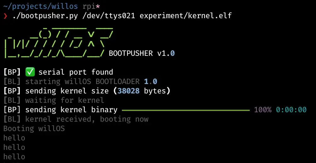
I spent too much time on the "pusher" UI part, I think 😅
ℹ️ Feel free to fork and edit this post if you find a typo, thank you so much! This post is licensed under the Creative Commons Attribution-ShareAlike 4.0 International (CC BY-SA 4.0) license.