SPI flash content analysis and firmware reconstruction
— Freiburg, GermanyI wrote a [Twitter thread about hardware hacking]1 some time ago.
The idea was to explain one way to obtain privileged access on a device. In
this case, the target was a cheap Chromecast-like device (more on that below)
and I “easily” got root access via UART.
This article explains how I reconstructed a modified firmware for this device.
Overview of the Chrome/Mira/Any-cast device
The target was a cheap Chromecast (or Miracast or Anycast) “clone” bought on Aliexpress (I am not sure because it was a “gift”). Such a device lets users cast audio and video on their TV as shown in Figure 1 (HDMI output). In addition to a HDMI connector, this device is bundled with an external WiFi adapter (USB).
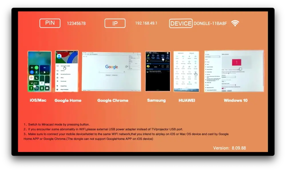 Figure 1: A screenshot of the default HDMI output (taken with a capture card)
When the device is powered on for the first time, it creates a WiFi network,
e.g., DONGLE-11BA8F. Users should first connect to this network with their
smartphone or laptop, and configure the device using a web app as shown in
Figure 2. This step is necessary to allow the device to connect to the user’s
WiFi network.
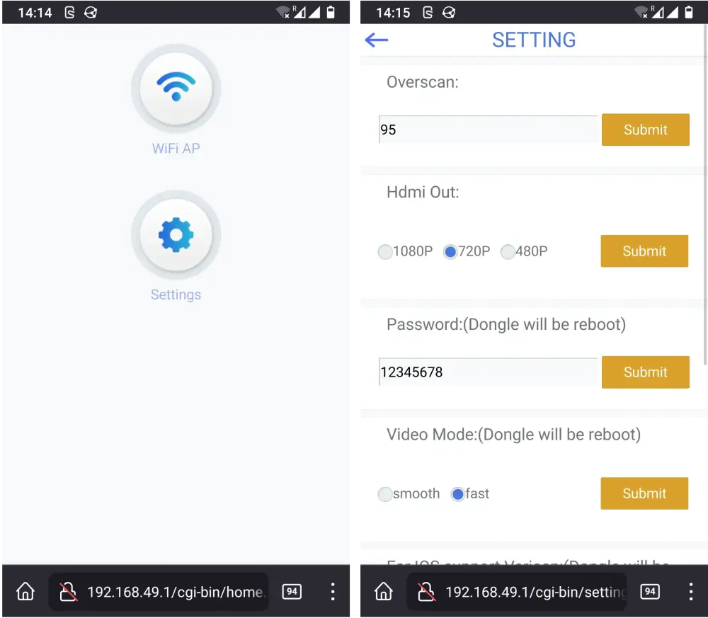 Figure 2: Two screenshots of the web application
Once the device has restarted and joined the user’s WiFi network, users can theoretically send audio or video to the device and have it played on TV. According to the manual, this device should work with the “Chromecast protocol” but it didn’t work that well for me.
I was able to cast audio and pictures but not video. Google Home wasn’t able to communicate with the device in a stable manner. I tried many different applications on both iOS and Android and I wasn’t able to achieve much. I tried to upgrade the device but the remote server was not found… These are the reasons why I decided to “hack” this device.
Besides having fun, my goal was to find ways to “fix” this device either by updating the software or re-purposing it. I knew it’d be complex but also that I’d learn a lot. At the time of writing, I didn’t achieve my goal yet but I made good progress.
I explained how I gained access to a Linux console in the Twitter thread so I am not going to repeat myself here. Instead, the rest of this blog post describes what happened next.
Diving into the content of the SPI flash
I was left with a full dump of the SPI flash (the storage component of this device) and many questions. I used binwalk to get an overview of the content of the SPI flash.
The dump contained a Linux kernel (the three first entries in the output below) and two file systems: Journalling Flash File System version 2 (JFFS2) and SquashFS.
$ binwalk flash.dump
DECIMAL       HEXADECIMAL     DESCRIPTION
--------------------------------------------------------------------------------
264192        0x40800         Linux kernel ARM boot executable zImage (little-endian)
280492        0x447AC         gzip compressed data, maximum compression, from Unix, last modified: 1970-01-01 00:00:00 (null date)
3292936       0x323F08        Flattened device tree, size: 49912 bytes, version: 17
4456448       0x440000        JFFS2 filesystem, little endian
5242880       0x500000        Squashfs filesystem, little endian, version 4.0, compression:xz, size: 10778932 bytes, 412 inodes, blocksize: 524288 bytes, created: 2020-12-02 03:03:01
I kindly asked binwalk to extract the SquashFS partition:
$ ls squashfs-root/
bin/  build.prop*  etc/  fonts/  lib/  usr/  vendor/
In the Twitter thread, I mentioned that the device was running Android. This
SquashFS partition is very likely the system partition. Among other things, it
contains the content of the web application described in the previous section.
Each page is a CGI ELF binary:
$ file squashfs-root/bin/home.cgi
squashfs-root/bin/home.cgi: ELF 32-bit LSB shared object, ARM, EABI5 version 1 (SYSV), dynamically linked, interpreter /system/bin/linker, stripped
After a few Google/GitHub searches, I had found extremely similar sources of these CGI files. None of these scripts seemed particularly interesting, though.
I also took a quick look at the JFFS2 partition, which appeared to be the data
partition (of an Android-based system) but I didn’t find anything useful either.
Last, I used fdtdump to explore the device tree, i.e. the “hardware configuration” of this device for the Linux kernel (Android uses the Linux kernel). This gives an idea of which hardware may be present and how it should be used by the kernel, and it could be useful information later.
After that, I looked at the structure of the SPI flash.
MTD partitions
Based on the kernel logs I had captured when I was using the Linux console over serial, I knew the content was divided into 5 different partitions: loader, kernel, data, system and misc.
[    0.379500] Creating 5 MTD partitions on "rk29xxnand":
[    0.379538] 0x000000000000-0x000000040000 : "loader"
[    0.380859] 0x000000040000-0x000000440000 : "kernel"
[    0.382175] 0x000000440000-0x000000500000 : "data"
[    0.383466] 0x000000500000-0x000000ffd000 : "system"
[    0.384697] 0x000000ffd000-0x000000ffe000 : "misc"
Out of 5 MTD partitions, 3 have been seen previously: kernel, data and
system. Note that the kernel partition starts at 0x40000 but binwalk
found the zImage at 0x40800. We’ll get back to that in a moment. For data
and system, the offsets in the binwalk output match the base addresses in
the logs above.
This time, I used dd to split the original dump into different binary files
based on the address ranges printed in the kernel logs above. I then looked at
each file individually, and made the following observations:
kernel.binis not recognized byfile, weird.- although
data.binandsystem.binare correctly detected as file systems byfile, the.binfiles extracted withddseem different than the files extracted withbinwalk. Maybe becausebinwalktried to find magic numbers and metadata (like the size of the content it has to extract)? I am not sure. misc.binis an “empty” binary file.
$ file *.bin
loader.bin:  data
kernel.bin:  data
data.bin  :  Linux jffs2 filesystem data little endian
system.bin:  Squashfs filesystem, little endian, version 4.0, xz compressed, 10778932 bytes, 412 inodes, blocksize :  524288 bytes, created :  Wed Dec  2 03:03:01 2020
misc.bin  :  ISO-8859 text, with very long lines, with no line terminators
Given I had already analyzed the “data partitions” (data and system), I
decided to study the loader and kernel partitions next.
The loader partition
I ran strings on the loader.bin file, which returned a few strings that I
already read before. Indeed, this partition contains the code that loads the
Linux kernel and some of the strings found in the binary appeared in the boot
logs collected over serial:
DDR Version 1.08 20170609
In
DDR2
396MHz
BW=16 Col=10 Bk=8 Row=13 CS=1 Size=128MB
OUT
0 BUILD: Apr 13 2018 09:17:13, version: 1.24
sfc nor id: c2 20 18 10 3c
g_spi_flash_info id 0x00c22018.
AddrMode: 0
ReadLines: 0
ProgLines: 0
ReadCmd: 3
ProgCmd: 2
blkEraseCmd: d8
secEraseCmd: 20
boot_media = 0x10
flash vendor_storage_init
OK! 21154
loader flag: 0x0
start_linux=====258615
multi-entries loader - fw_status: 0x1, kernel_addr 200, 259 ms
enter LoadKernel @263 ms
hdr.loader_load_size= 2efa00
hdr.loader_load_addr= 62000000
load kernel data done @1043 ms
run kernel@0x62000000 =====1043 ms
loader update successfully =====1046 ms
<hit enter to activate fiq debugger>
[    0.000000] Booting Linux on physical CPU 0xf00
...
It looks like the bootloader is named “DDR” and the version is 1.08. I found
binaries for other versions of this bootloader on the web but not for
the version I had (huh?), and no source code.
I also ran hexdump on loader.bin and was faced with the following output:
00000000  52 4b 46 50 e4 07 0c 02  0b 03 0e 00 19 00 05 10  |RKFP............|
00000010  00 02 00 00 01 00 00 00  f0 7f 00 00 80 00 00 00  |................|
00000020  06 00 00 00 00 00 00 00  01 00 00 00 00 00 00 00  |................|
00000030  00 00 00 00 00 00 00 00  00 00 00 00 00 00 00 00  |................|
*
000001f0  00 00 00 00 00 00 00 00  98 45 32 7b a8 8a fb fa  |.........E2{....|
00000200  76 65 6e 64 6f 72 00 00  00 00 00 00 00 00 00 00  |vendor..........|
00000210  00 00 00 00 00 00 00 00  00 00 00 00 00 00 00 00  |................|
00000220  01 00 00 00 08 00 00 00  38 00 00 00 00 70 00 00  |........8....p..|
00000230  00 00 00 00 01 00 00 00  00 00 00 00 00 00 00 00  |................|
...
I tried to find more information about the RKFP magic number. There isn’t a
lot of information about it. This seems to be a proprietary image format but its
structure is partially known and open source. I found the definitions of the
different structures in rkflash_blk.h (Linux kernel) and
this page helped a lot by providing additional context!
The kernel partition
I read the kernel.bin file with hexdump. The first few bytes are shown
below:
$ hexdump -C part-kernel.bin
00000000  4b 45 52 4e 45 4c 00 00  00 00 00 00 00 00 00 00  |KERNEL..........|
00000010  00 00 00 62 00 fa 2e 00  cc ec ad 80 20 00 00 00  |...b........ ...|
00000020  7a 46 9d 1b 84 4d be a7  59 81 3a 48 d2 19 67 a4  |zF...M..Y.:H..g.|
00000030  79 9c d3 78 d9 3f d6 5a  c7 34 03 ec 1b 09 84 b9  |y..x.?.Z.4......|
00000040  00 00 00 00 00 00 00 00  00 00 00 00 00 00 00 00  |................|
...
This looks like some kind of partition header. That’s odd because (1) the other
partitions don’t appear to have any header like that, and (2) I only found
RockChip tools that deal with images with KRNL as magic number, not KERNEL.
Ugh.
In the hexdump output above, I noticed two values on the second line that
looked familiar. Indeed, in the bootloader logs, there were these two lines:
hdr.loader_load_size= 2efa00
hdr.loader_load_addr= 62000000
The load address is therefore at offset 0x10 in this “kernel header”, and the
(kernel?) size is at offset 0x15. Then we have another 4 bytes, which seems to
be the CRC for this header. The next 4 bytes hold a value of 0x20 and that
looks like the length of the following bytes (from 0x20 to 0x40). Some
checksum, maybe? This could be the length of a SHA-256 hash.
After this header, there is some padding until offset 0x800 where we find some
ARM instructions (00 00 A0 E1). This explains why binwalk found the kernel
at 0x40800 before.
At this point, I had enough information about the content of the SPI flash. As stated at the top of this blog post, my goal was to fix this device. Writing a parser for these RKFP images would be a good first step to be able to update the firmware eventually.
Parsing RKFP images
I developed a tool in C to print information about RKFP images. I also found two other similar (SPI flash) dumps in the wild, allowing me to have more examples while developing my tool. In particular, it turned out that the image I had dumped myself had a CRC mismatch 😅
$ ./build/cli info flash.dump

Input file:
  name: flash.dump
  size: 16777216 bytes

Header:
  firmware tag           : RKFP
  firmware version       : 16.05.25
  release date           : 2020-12-02 at 11:03:14
  size                   : 512 bytes
  partition_offset       : 1 sectors
  backup_partition_offset: 32752 sectors
  partition_size         : 128 bytes
  partition_count        : 6
  fw_size                : 0 bytes
  partition_crc          : 0x7B324598
  header_crc             : 0xFAFB8AA8

CRC:
  WARNING! header CRC mismatch (got 0x74B94941)
  partition CRC: OK

Partition #00 - 0x00001000-0x00008000
  name     : vendor
  type     : 0x01
  offset   :     4096 bytes (0x1000)
  size     :    28672 bytes (0x7000)
  data size:    28672 bytes (0x7000)
  property : 0x00

Partition #01 - 0x00008000-0x00038000
  name     : IDBlock
  type     : 0x02
  offset   :    32768 bytes (0x8000)
  size     :   196608 bytes (0x30000)
  data size:    86016 bytes (0x15000)
  property : 0x00

Partition #02 - 0x00040000-0x00440000
  name     : kernel
  type     : 0x04
  offset   :   262144 bytes (0x40000)
  size     :  4194304 bytes (0x400000)
  data size:  3080708 bytes (0x2F0204)
  property : 0x00

Partition #03 - 0x00440000-0x00500000
  name     : data
  type     : 0x08
  offset   :  4456448 bytes (0x440000)
  size     :   786432 bytes (0xC0000)
  data size:   786432 bytes (0xC0000)
  property : 0x00

Partition #04 - 0x00500000-0x00FFD000
  name     : system
  type     : 0x0C
  offset   :  5242880 bytes (0x500000)
  size     : 11522048 bytes (0xAFD000)
  data size: 10780672 bytes (0xA48000)
  property : 0x00

Partition #05 - 0x00FFD000-0x00FFE000
  name     : misc
  type     : 0x0F
  offset   : 16764928 bytes (0xFFD000)
  size     :     4096 bytes (0x1000)
  data size:        0 bytes (0x0)
  property : 0x00
Most partitions were not new because they were listed as “MTD partitions” and I
had already analyzed some of them. The tool found 6 RKFP partitions, though.
Instead of having a loader partition, we had two partitions: vendor and
IDBlock. “ID Block” is apparently a header for Rockchip BootRom.
Next, I wrote a new command (extract_rkfp) to extract the actual data located
in each RKFP partition. It is worth mentioning that I later found the
rkflashtool project, which offers a tool to unpack RKFP images too (among
other things). Both this tool and mine were producing identical partition
files.
At this point, I was able to read information from a RKFP image, verify the different CRCs and extract the data contained in each partition. I had two options: (1) stop there and forget about this project, or (2) find out how to make a RKFP image 😬
Reconstructing RKFP images
I tried to reconstruct the RKFP images I had (the one I dumped and two I found
online). My idea was to invert the “read” process by appending the different
RKFP partitions extracted with make_rkfp after having written a “RKFP header”.
Obviously, this didn’t work… I used VBinDiff (a lot) to compare the
original image and the one I had reconstructed with my tool. The header appeared
to be correct but there were differences in the IDBlock partition and in some
other locations.
I realized that the IDBlock partition was special: although it had a data size
of N, its actual size was almost three times bigger and after having inspected
its content, I had the impression that there was more data than what the
partition metadata was saying. Some more searches about this mysterious
setting.ini file mentioned here made me conclude that there
were probably two loaders. Given that this partition likely contained
proprietary code that I needed anyway but didn’t necessarily need to change, I
adjusted my tool. I special-case’d the IDBlock partition so that the entire
partition was (1) extracted with extract_rkfp, and (2) written with
make_rkfp.
I could then generate a RKFP image that looked almost like the original one. The images I found online had extra “backup metadata”, which I didn’t have in the image coming from my device. I wrote code for that, too.
I was kinda confident with my tool but I hadn’t tried the new images on the device yet so its effectiveness was purely theoretical.
A breakout board for SOIC-16
In order to verify that my tool was producing correct firmware, I needed a way to write to the SPI flash chip and then boot the device. Near the end of the Twitter thread, the flash had been desoldered. Soldering and desoldering the flash every time was not an option, and I couldn’t properly use flashrom when the flash was soldered on the device.
I decided to design a small PCB to get access to the flash pins using a 1.27mm 16-pin socket, which would be soldered on the device (see Figure 3). The same board could also be reused with a plug on one side and the flash chip on the other side (see Figure 4).
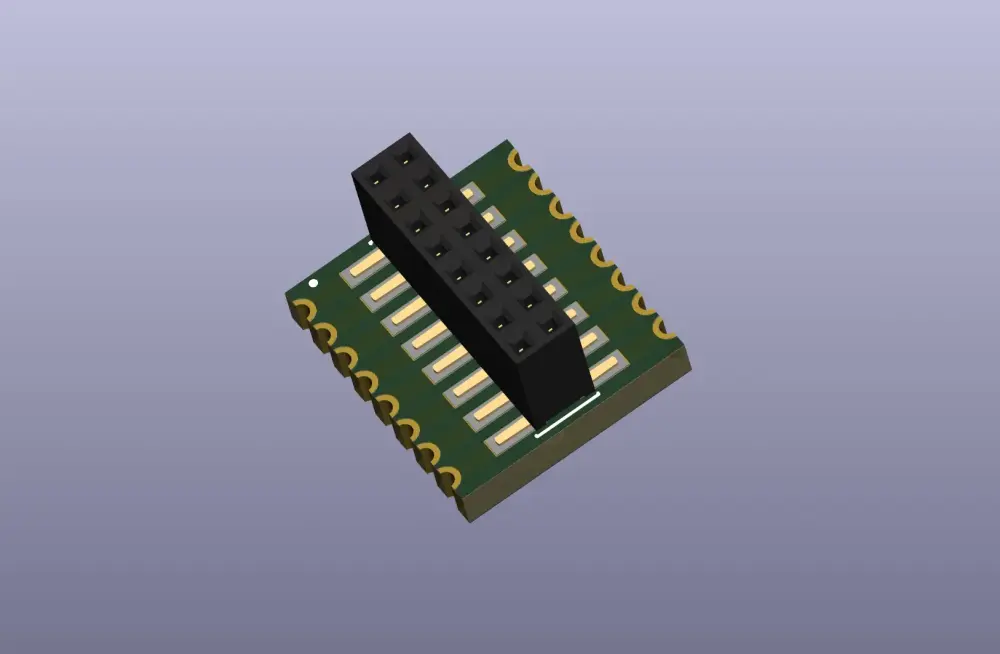 Figure 3: The 3D view of the breakout board for SOIC-16
It was the first time I designed a PCB with castellated holes. OSH Park did an amazing work on such small boards (about the size of 1 cent coins) 😍
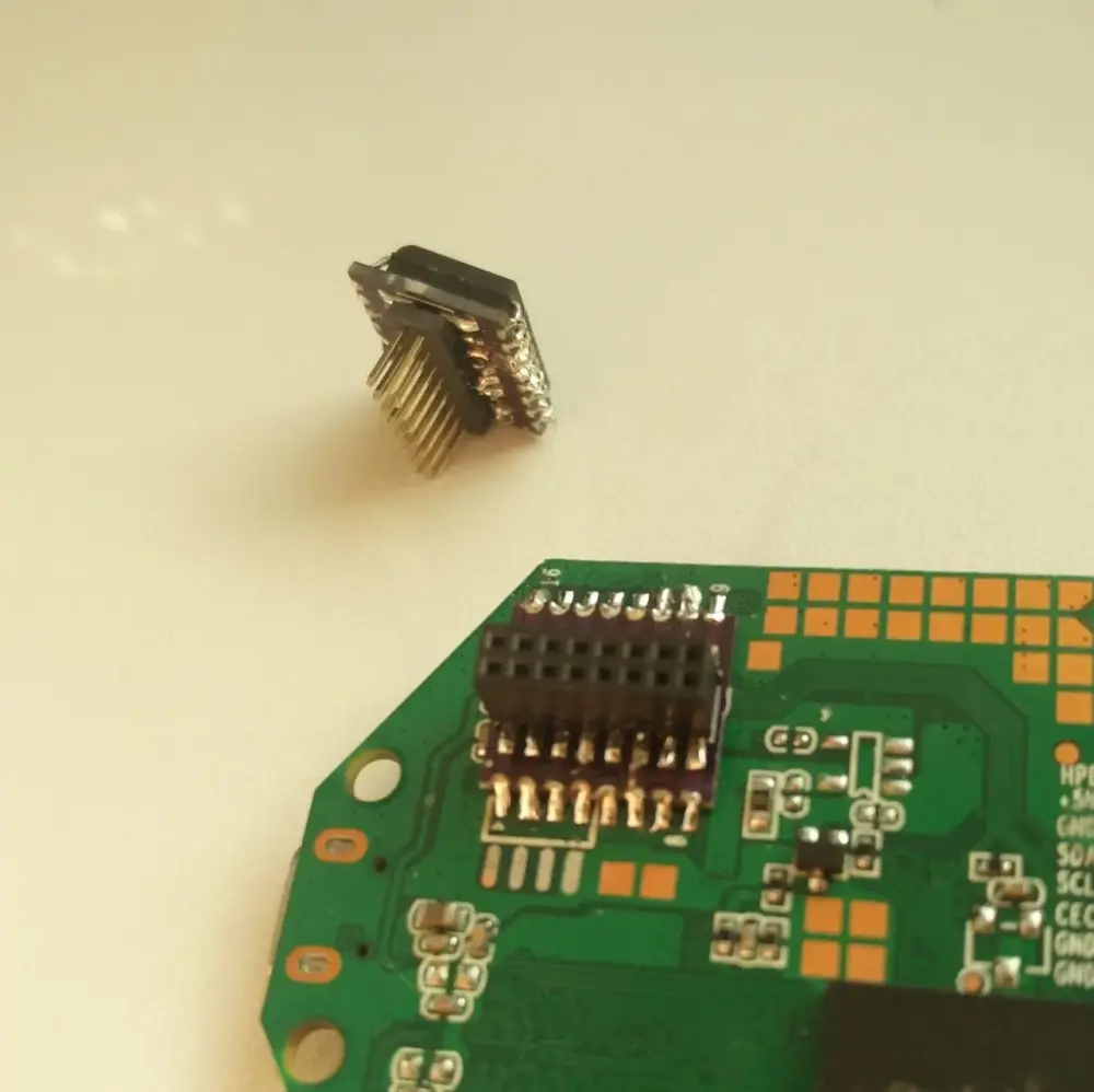
second breakout board
holds the SPI flash + a plug on the other side
With these breakout boards assembled (see Figure 5), I could easily write to the flash and test my changes on real hardware. Before that, I made sure that the device could still boot with the original firmware (still present on the flash).
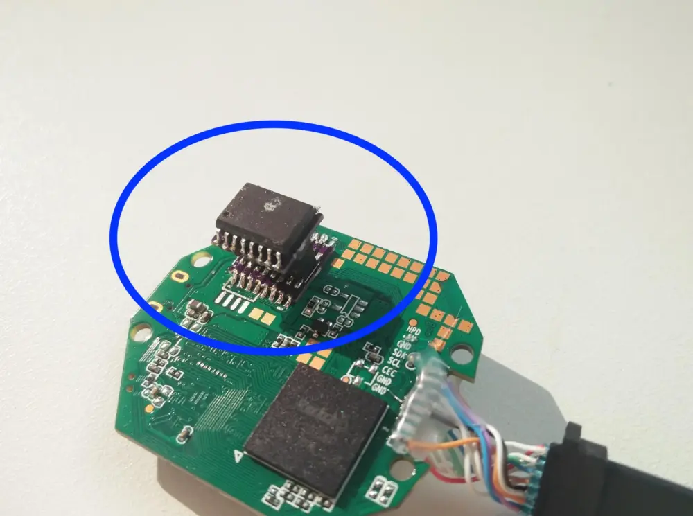 Figure 5: The SPI flash mounted on the device (blue circle)
I then used flashrom to put the reconstructed (unmodified) firmware on the SPI flash and I powered on the device. Success! The device booted and everything seemed to work as before.
My next experiment was about producing and booting a modified firmware.
Modifying the system partition
I opted to change the system partition. The first step was to know which options to use to rebuild the SquashFS partition:
$ unsquashfs -s part-system.bin
Found a valid SQUASHFS 4:0 superblock on 500000.squashfs.
Creation or last append time Wed Dec  2 04:03:01 2020
Filesystem size 10778932 bytes (10526.30 Kbytes / 10.28 Mbytes)
Compression xz
        Dictionary size 524288
        Filters selected: arm
Block size 524288
...
I changed a file in the extracted content and then rebuilt the partition:
$ mksquashfs squashfs-root new-system-partition.bin -comp xz -Xbcj arm -b 524288 -all-root
I then reused the make_rkfp command to create a new RKFP image and loaded it
on the SPI flash, then put the flash back on the device and powered it on. 3..
2.. 1.. Success! 😎
 Figure 6: HDMI output with the modified firmware
Work in progress
Only the system partition has been altered in the previous section but the
data partition could have been equally modified. I had no interest in changing
the loader partition and the misc one was empty. This leaves us with the
kernel partition.
I added a extract_kernel command to my tool to extract the data from the
kernel partition. This was a requirement to understand how to make such a
kernel partition in the future, the main motivation being to eventually update
the version of the Linux kernel.
The extracted data appears to be a zImage with DTB files appended to it. I am
not too sure how that has been generated yet, maybe just cat zImage *.dtb > kernel?
A initial ramdisk seems to be part of that same zImage too, and it
contains different init.*.rc files.
The next steps will be to build a new Linux kernel that looks like the extracted one, and see if that works.
Conclusion
After having gained root access on this device, I have been able to modify the
original firmware. Out of 5 MTD partitions, all but two have been fully analyzed
(loader and kernel). I designed a breakout board to easily verify firmware
produced with a tool I created specifically for this project. This was also a
good excuse to learn about modern CMake 😉
As mentioned before in this article, I was not too interested in the loader
partition, hence my focus on the kernel partition near the end. In the future,
I want to build a new kernel image and load it on the device. There are two
known issues so far: (1) building the right (Android) kernel for the device, and
(2) creating a kernel partition for the RKFP image. We’ll see how it goes…
Last but not least, both the tool and the KiCad files have been published on GitHub. Enjoy!
-
This used to be a link to a Twitter thread from me. I documented how I gained (root) access on a cheap device, which involved hardware and software skills. ↩
ℹ️ Feel free to fork and edit this post if you find a typo, thank you so much! This post is licensed under the Creative Commons Attribution-ShareAlike 4.0 International (CC BY-SA 4.0) license.